How to use the L298N motor driver module
This module allows you to independently manage two motors of up to 2A each in both directions. Supply range may vary between 5V and 35V, enough for most DC motor projects.


Apps and platforms
Arduino IDE
Project description
Main article: $ How to use the L298N motor driver module $
The L298N Motor Driver is a controller that uses an H-Bridge to easily control motors direction and PWM to control the speed. This module allows you to independently manage two motors of up to 2A each in both directions. Supply range may vary between 5V and 35V, enough for most DC motor projects.
Prerequisites
We strongly recommend reading our article about PWM: $ What is PWM and how it works $
Pinout
In first place, let’s understand the meaning of each pin provided on L298N board.
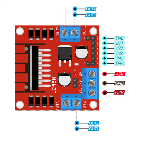 L298N pinout
 L298N pins description
The spinning direction of the motor can be controlled by applying logic HIGH or logic LOW to IN1/IN2 (motor A) and IN3/IN4 (motor B) inputs as shown on table.
 L298N spinning direction
The speed control pins ENA and ENB are used to turn on/off the motors and control their speed with Pulse Width Modulation (PWM). That means that motor will spin at full speed with HIGH and stop with LOW. Usually the module comes with a jumper on these pins that connects them directly to HIGH value. If you want to keep the speed control of your motors remove the jumper and connect ENA and/or ENB pins to PWM. Otherwise the motor will always spin at full speed.
Voltage regulator
The module includes 5V regulator that can be enabled/disabled using a jumper:
- With jumper: the regulator is enabled and +5V pin acts as output. It can be used to power an Arduino or other circuitry that needs 5V power. Note: with power supply greater than 12V the jumper must be removed to prevent damage to the onboard regulator.
- Without jumper: the regulator is disabled and +5V pin acts as input, expecting 5V to be supplied.
Take into consideration that the L298N module has voltage drop of approximately 2V. With 12V power supply the motors will receive approximately 10V which means that we won’t be able to get the maximum speed.
Wiring schema
Having a solid understanding of each pin and how the module works we can proceed with the wiring.
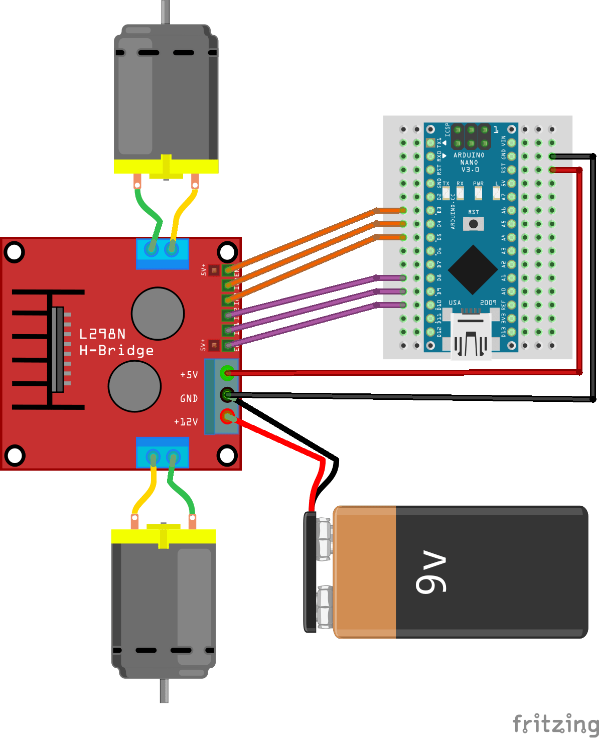 L298N wiring schema
ENA and ENB are connected to the Arduino Nano PWM pins and IN1/IN2/IN3/IN4 to common digital pins. We are using 9V battery and the jumper is in place, so we can use +5V pin to power the Arduino too.
Arduino code
The code is quite simple and it does not require any external library to work. We’ve defined a struct (called motor) which will represent the speed and the direction for each motor.
- setup() function marks necessary pins as output and initialize motors with default values.
- loop() main function tests motors speed and switch direction.
- sendToMotorA() function wraps pin information for motor A.
- sendToMotorB() function wraps pin information for motor B.
- increaseMotorsSpeed() function gradually increases the speed for both motors.
- decreaseMotorsSpeed() function gradually decreases the speed for both motors.
Some explanatory messages has been added to be able to debug the process in serial monitor.
// Motor A
#define ENA_PIN 10 //PWM
#define IN1_PIN 9
#define IN2_PIN 8
// Motor B
#define ENB_PIN 3 //PWM
#define IN3_PIN 4
#define IN4_PIN 5
struct motor {
	 byte speed = 0;
	 struct {
	   byte input1 = LOW;
	   byte input2 = LOW;
	 } direction;
};
motor motorA, motorB;
void setup()
{
	 Serial.begin(115200);
	 // Set PWM & direction pins to output for both motor
	 pinMode(ENA_PIN, OUTPUT);
	 pinMode(IN1_PIN, OUTPUT);
	 pinMode(IN2_PIN, OUTPUT);
	 pinMode(ENB_PIN, OUTPUT);
	 pinMode(IN3_PIN, OUTPUT);
	 pinMode(IN4_PIN, OUTPUT);
	 // Init with default values
	 sendToMotorA();
	 sendToMotorB();
}
void loop()
{
	 Serial.println("Motors are stopped now");
	 Serial.println("Set direction FORWARD");
	 delay(2000);
	 setMotorDirectionForward(motorA);
	 setMotorDirectionForward(motorB);
	 Serial.println("Gradually increase motors speed to max");
	 increaseMotorsSpeed();
	 Serial.println("Motors are on full speed now");
	 delay(2000);
	 Serial.println("Gradually decrease motors speed to min");
	 decreaseMotorsSpeed();
	 Serial.println("Motors are stopped now");
	 Serial.println("Set direction BACKWARD");
	 delay(2000);
	 setMotorDirectionBackward(motorA);
	 setMotorDirectionBackward(motorB);
	 Serial.println("Gradually increase motors speed to max");
	 increaseMotorsSpeed();
	 Serial.println("Motors are on full speed now");
	 delay(2000);
	 Serial.println("Gradually decrease motors speed to min");
	 decreaseMotorsSpeed();
}
void sendToMotorA()
{
	 sendToMotor(motorA, ENA_PIN, IN1_PIN, IN2_PIN);
}
void sendToMotorB()
{
	 sendToMotor(motorB, ENB_PIN, IN3_PIN, IN4_PIN);
}
void increaseMotorsSpeed()
{
	 for (int speed = 0; speed <= 255; speed++) {
	   setMotorSpeed(motorA, speed);
	   setMotorSpeed(motorB, speed);
	   sendToMotorA();
	   sendToMotorB();
	   delay(20); // Add small delay between changes
	 }
}
void decreaseMotorsSpeed()
{
	 for (int speed = 255; speed >= 0; speed--) {
	   setMotorSpeed(motorA, speed);
	   setMotorSpeed(motorB, speed);
	   sendToMotorA();
	   sendToMotorB();
	   delay(20); // Add small delay between changes
	 }
}
Note: the snippet is part of Arduino project located in our $ GitHub repository $ with the code separated in different logical files.


